05 Sep 2021
I’ve been exploring Unity a fair bit over the last month, as game development is a skill I’d like to have. My son has also been really interest in the solar system and different orbits.
If you’ll permit a tagent - we got into a discussion about how everything in the solar system orbits the barycenter, rather than the sun. And my son seemed to understand, in part thanks to these NASA visualizations: https://spaceplace.nasa.gov/barycenter/en/ And that of course got me on a tangent of thinking about why we lie to kids (I’m not being provocative, the Wikipedia entry is literally lie-to-children). I mean, we don’t teach them that things revolve around the earth – frankly, I think it’s cooler to understand that things orbit around a common center of mass, rather than the sun because “I said so”, but what do I know…
Back to the main topic. I was going through a Udemy course on mobile games in Unity (not an affiliate link), and built out a barebones Angry Birds clone. Naturally, once I’d gotten it loaded on my phone, my four-year-old was one of the first beta testers.
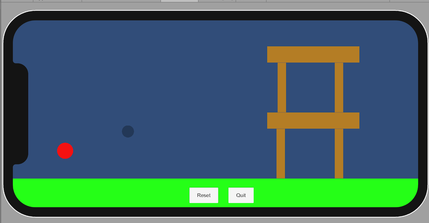
The ball itself operates on a pivot joint, so the intended use case is for you to draw back the ball – slingshot-style – and let it fly toward the structure. Unity physics takes care of the rest. And my four-year-old was immediately excited and laughing, but it did not remotely occur to him to draw back on the ball. Instead, he excitedly dragged his finger across the structure. And because the game is fairly simple without too many restrictions, the ball obligingly followed along with him, allowing him to knock out the tower with ease.
It was interesting to me because the slingshot mechanic was intuitive for me and my wife, but nothing in the UI directly communicates that. Effectively, my son taught me a good lesson about affordances.
I’d love to move on to my original goal of building a barycenter-based orbital simulator for my son to play with, but I’m kinda interested in evolving this mini-game now, based on my son’s excitement. And rather than fix the UX “bug”, I think I’d prefer the game to operate the way that my son expects: if he flings an object, it should preserve it momentum. My hope is that should’t be too difficult – just a matter of tracking Δposition across two frames, and applying an appropriate force before triggering Unity’s normal physics system. So maybe my son taught me two lessons: when folks find a bug - maybe the original behavior was ill-conceived in the first place!
11 Mar 2021
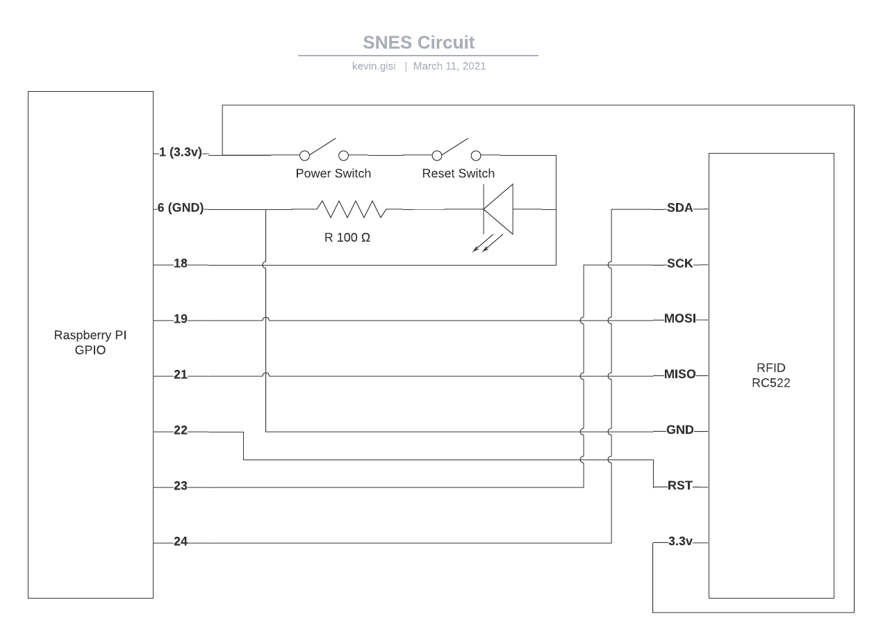
I started to lay out a circuit diagram for the remainder of the SNES. In diagramming things out, it seems possible I could support the power, reset, and power LED with only the use of a single additional GPIO pin. Thinking about it, the reset button only matters when the power is on, so it can just be wired in series with the power button. Likewise with the LED - it should be on whenever the power/reset combo are on, so there’s no need to actually control it from the Pi (unless in the future we want to use it as a debugging indicator or something fancy like that).
Here’s what I came up with:
A few immediate caveats:
- The diagram shows both the power and reset switches as being normally open - that is, they do not allow signal to flow through. In which case, the behavior would be off. What we ideally want is the power button to be normally open, but the reset button to by normally closed. If not, we can do some inverting of the signals to get what we want. But it does mean our diagram is inaccurate.
- It’s possible the LED on the SNES is 5v. If so, we can still use the power signal to drive it; we’ll just want to use a 5v signal to release a 3.3v output to the GPIO pin, or use a 3.3v signal to release a 5v output to the LED.
- Do we perhaps have to worry about current if we’re splitting stuff across multiple peripherals? This is where my complete and total ignorance really comes into play. Quick Googling suggests we want to keep total current below 50mA, and the RF reader peaks at 26mA, so I’m gonna guess we’re fine here.
Not a huge amount to do in the meantime until I’ve got a spare SNES here I can use for parts. Once that’s done, I’m eager to see if we can use the existing power and reset mechanical switches and see what we’re working with. From there, we should be able to determine what needs inversion, etc.
10 Mar 2021
Great news — it looks like NFC stickers are going to be the right path forward. Received a bundle today, stuck a sticker on the inside of a cartridge, and my iPhone can pick it up a centimeter away from the outside of the cartridge. Next step is to try to verify with a reader chip.
Unfortunately, the chip I got doesn’t have a datasheet. Thankfully, it’s a common enough model, there’s a guide to its use with the Raspberry Pi already. Lucky me, I’ve learned a little bit about the I2C protocol (which the EEPROMs use), and now I’m learning a bit about the SPI protocol.
After hooking up the RC522 chip via the breadboard and lovingly plagiarizing some code from the tutorial, I got things working. Mostly. While I could pull a unique ID from the NFC stickers, the library did announce an AUTH FAILURE. It was reporting it on STDOUT, so I could have just tried to suppress the error, but it seems it’s related to the NFC stickers I have being an older standard. I came across this reported issue, and was able to cobble together a solution based around the workaround listed there (the relevant issue).
Remember: we don’t need to actually write any data to these stickers. We just need a unique serial number that the Raspberry Pi can use to drive its own behavior. Merging that with our existing app code, here’s where we’re at:
#!/usr/bin/env python3

import subprocess
import RPi.GPIO as GPIO
from mfrc522 import MFRC522
from time import sleep

ROM_DICT = {
    '04:6c:6a:8a:92:4c:68:80:36:48:00:00:e1:10:3e:00': 'Super Mario World (USA).sfc',
    '04:53:6c:b3:92:4c:68:81:37:48:00:00:e1:10:3e:00': 'Donkey Kong Country (U).smc'
}

def main():
    try:
        # Await power on
        cartridge_id = get_nfc_id()
        print("CARTRIDGE is %s"%cartridge_id)
        rom = ROM_DICT[cartridge_id]
        print("ROM is %s"%rom)
        game = run_game(rom)
        game.wait()
        # On power off, kill the subprocess
        # On reset, restart the subprocess
    finally:
        cleanup()

def run_game(rom):
    return subprocess.Popen([
        '/opt/retropie/emulators/retroarch/bin/retroarch',
        '-L', '/opt/retropie/libretrocores/lr-snes9x2010/snes9x2010_libretro.so',
        '--config', '/opt/retropie/configs/snes/retroarch.cfg',
        '/home/pi/RetroPie/roms/snes/%s'%(rom),
        '--appendconfig', '/dev/shm/retroarch.cfg'])

def get_nfc_id():
    reader = MFRC522()
    while True:
        status, _ = reader.MFRC522_Request(reader.PICC_REQIDL)
        if status != reader.MI_OK:
            sleep(0.1)
            continue
        status, backData = reader.MFRC522_Anticoll()
        buf = reader.MFRC522_Read(0)
        reader.MFRC522_Request(reader.PICC_HALT)
        if buf:
            return(':'.join(format(n, '02x') for n in buf))

def cleanup():
    GPIO.cleanup()

if __name__ == '__main__':
    main()
I opened up a second cartridge to attach a second sticker, and gave it a whirl. Thrilled to report that it works as-expected! Assuming that we can mount the reader within a centimeter of the back of the SNES cartridge, we’re good to go!
We’ll revisit the script at a later point when we’ve moved a bit further on with the housing. We’ll want to wire up the power and reset buttons — as well as the power indicator light — to some of the remaining GPIO pins, and then update our script to support the interrupts.
Next we have a big decision on our hands: are we modding an existing console, or building ourselves something new?
09 Mar 2021
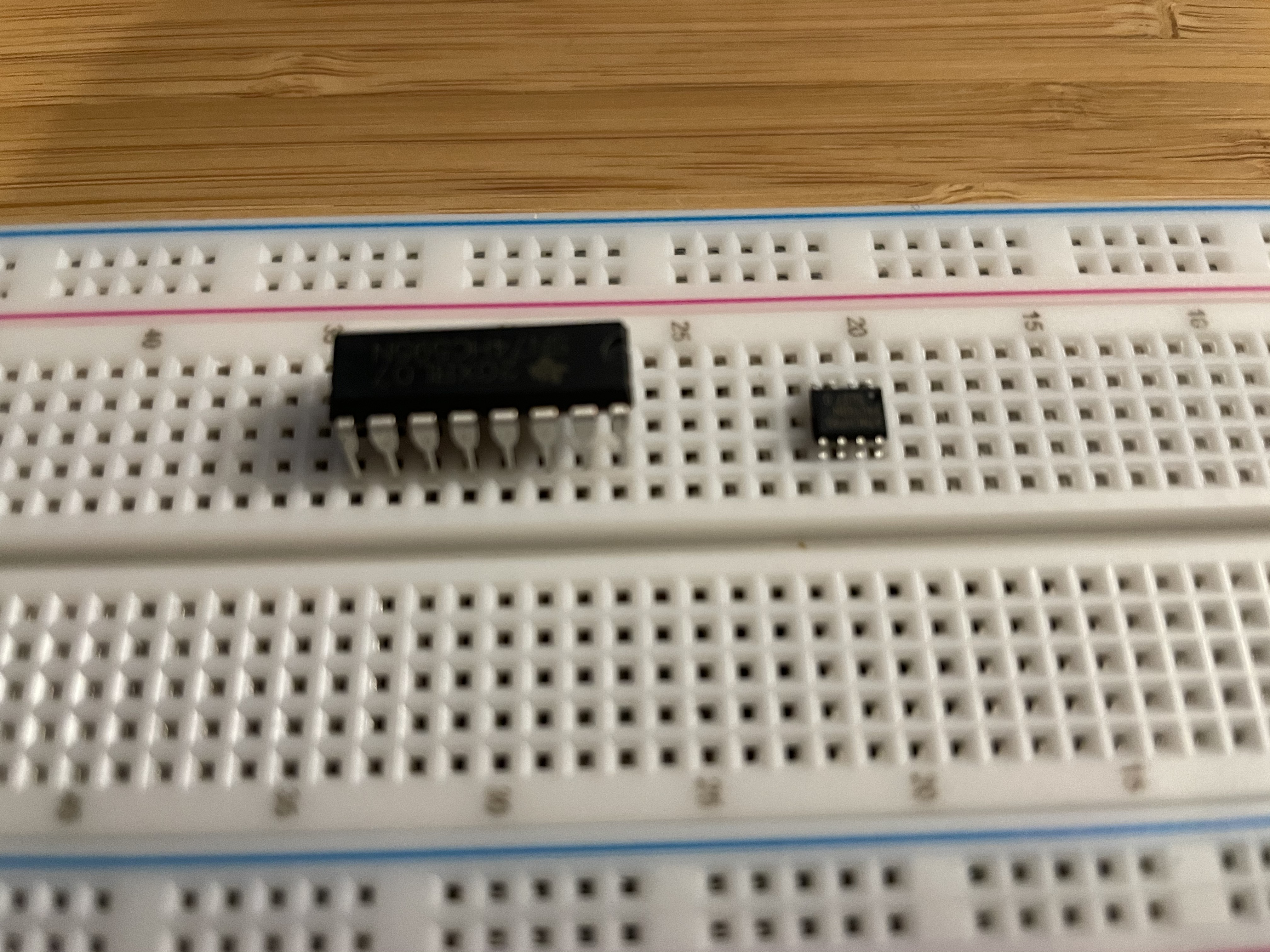
There is a standard size of integrated circuit called a “DIP”. The EEPROMS that I ordered were not that size. Rather, they are SOIC, which is significantly smaller. As a result, I can’t really use ‘em. Can’t use them in a breadboard without an adapter, and don’t really trust a soldering newbie like myself to manage those tiny pins, whether on an adapter or on an eventual PCB. We’d already come up with several reasons to want to avoid a PCB solution anyway though, so we’ll try out some other approaches before ordering a new set of EEPROMs.
The Raspberry Pi 4 arrived today. Thus far, I’m a little underwhelemed. Managed to make the same modifications to it that I did to the RPi3, and got Super Mario World running via Python script. However, the RPi4 has heat issues — a few minutes into playing I noticed significant dropped frames, and the system started alerting me to overheating. Pulled the plug around 85°C. It has higher power draw as well, being a faster device.
This isn’t the Pi 4’s fault; the case does come with heatsinks and a fan which I could set up. And it’s designed to draw more power and run faster. It’s doing its job. But it’s probably overkill for running SNES emulation. And to be completely fair, while the RPi3 wasn’t overheating, it did let me know I was undervolting it thanks to a shoddy USB charger. Didn’t cause any performance issues, but perhaps it contributed to lower heat.
So there’s some potential device triage to do. I’d love to keep the SNES fanless, given the original console is as well. But let’s get something working, and then we can scale it back to cheaper hardware.
08 Mar 2021
I’m at a bit of a roadblock moving forward with the emulator project while I wait for hardware to arrive. But it hasn’t stopped me doing some thinking about the right path forward.
We’ve demonstrated we can launch a specific ROM via a Python script, and that we can power it off and on, reset, etc. Wiring up those GPIO pins should be reasonably straightforward. But the remaining gap is around how we can read an identifier off a physical cartridge.
Standard SNES cartridges have contact points at the bottom which slide into an appropriate socket in the SNES. The contact points where electrical signal passes through are electroplated hard gold, which can handle the abrasion of frequent insertion and removal. This is, however, a rather expensive process. Some PCB prototype manufacturers don’t even offer hard gold plating - though many do provide electroless nickel immersion gold, which operates in a similar way but can’t stand up to frequent wear and tear. If we were looking to mate two circuit boards together permanently, only decoupling them for maintenance, ENIG would work just fine. A quick quote for hard gold plating though (such as on PCBgogo) sees an initial price of around $250, for a mere 5 boards. We could get 100 boards for $284, so it’s mostly the overhead of the process itself; we could manage more at scale.
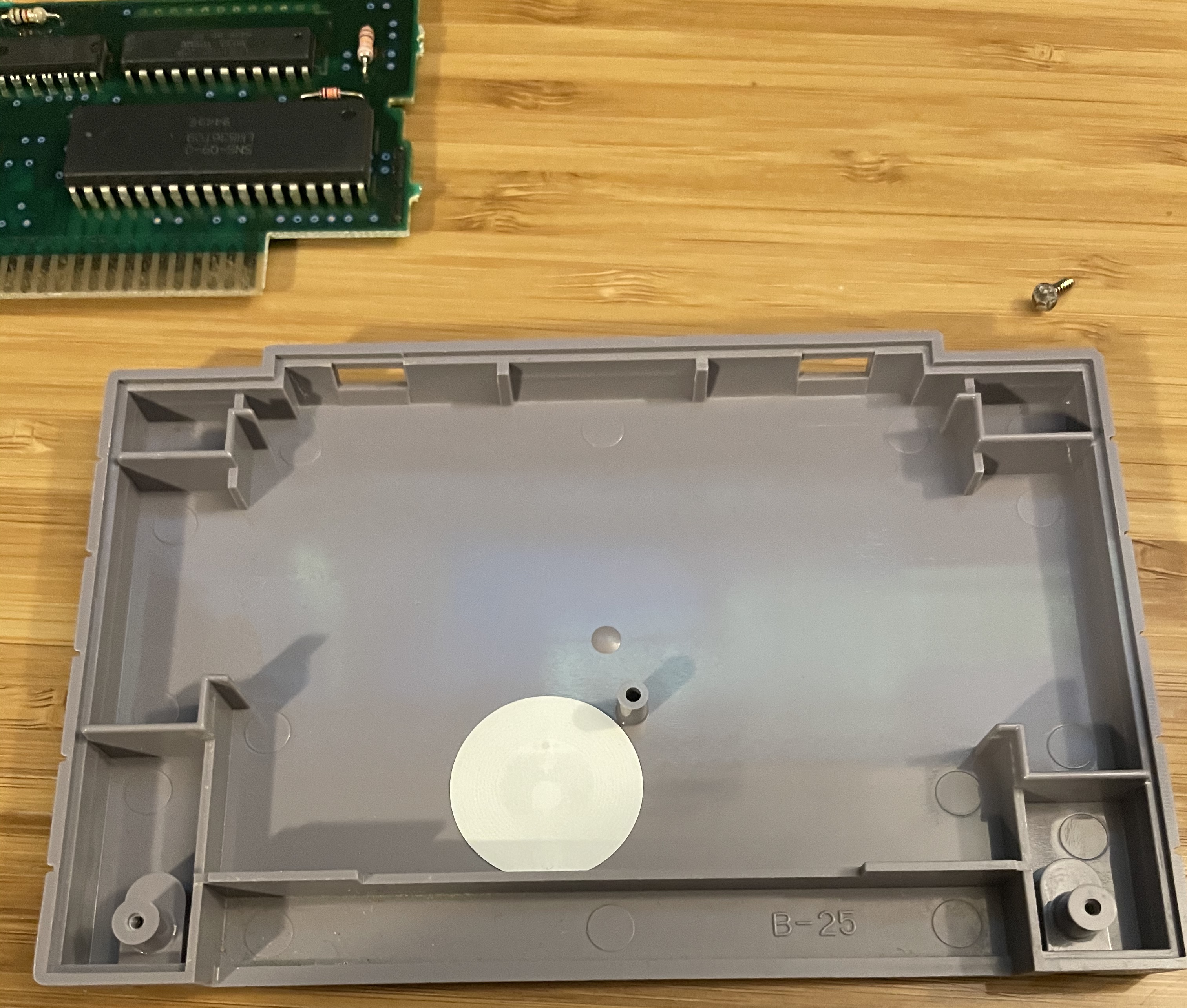
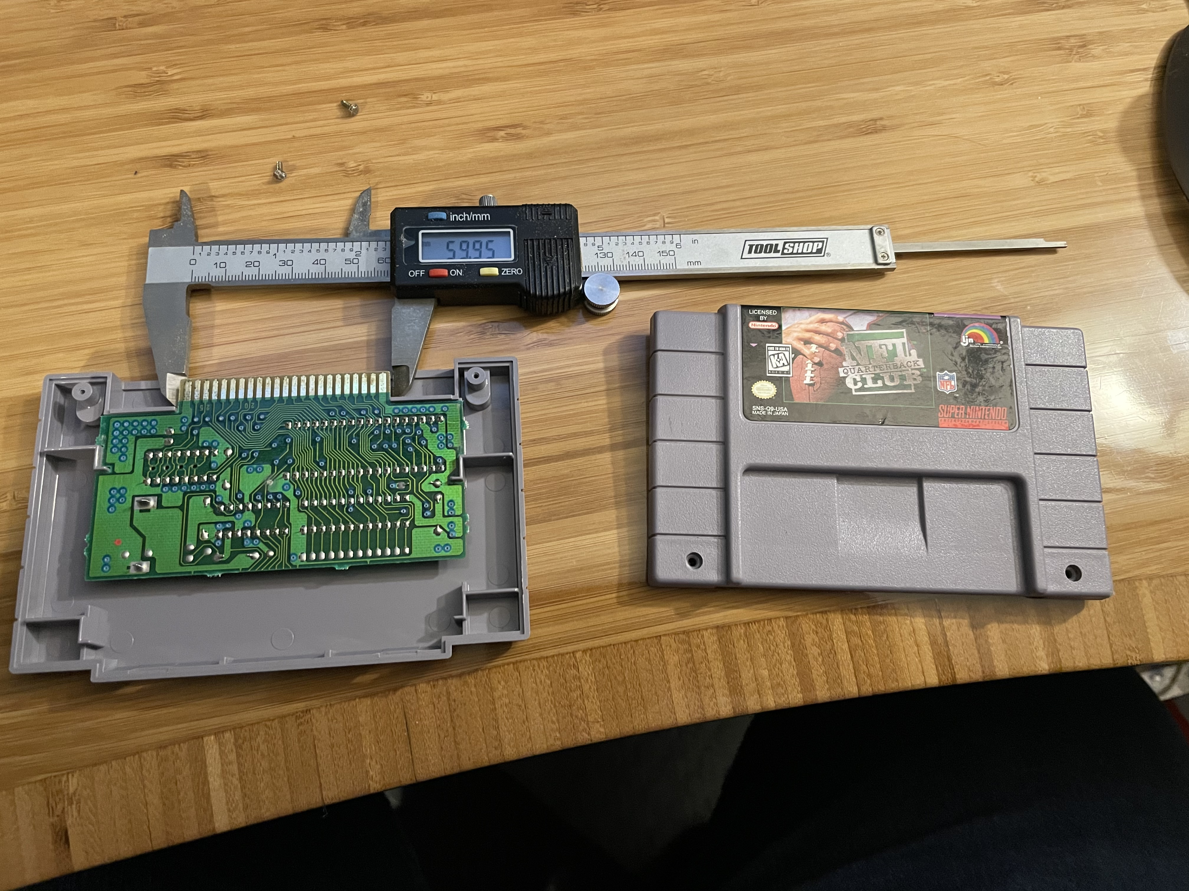
So I got to thinking about alternatives for how we might encode some data. For context, here’s the interior of a SNES cartridge.
Let’s assume we were 3d printing the circuit board. We could leave notches in the mating surface, and then use push buttons to measure where the notches are. Each board would have to be printed with a unique pattern, but in theory we could get a number of bits equal to the size of the buttons. There were less than a thousand SNES games released into the US market, so we’d need at-most 11 buttons. One button to detect the presence of a cartridge, and 10 buttons to uniquely identify a game (2^10 being 1024).
However, the springs of the buttons would exert at least some upward force, and presumably over time they would start to wear down. Probably better is if we were able to avoid mechanical contact at all.
IR Break Beam
Thinking about my son’s toys, there are a a few that use cutouts in paper to actually signal the device what it ought to do (I’m sure there’s a term-of-art for this “each card, cartridge, whatever has a pattern that sends a pattern to switches” idea, but thus far Google hasn’t helped me). Much like the Hollerith punch cards that our ancestors used to program their Macbooks.
So okay, what about using interposition. The presence or absence of a hole signifies the bit. Looking at how that used to be measured, there’s a mechanical process that used brushes to complete a circuit through the hole — that seems prohibitively complex — but there’s also mention of photoelectric sensors. We can detect whether an infrared beam is interrupted! This has potential, but we’ll need to verify a few things:
-
How many IR beams could we fit next to each other?
-
How worried do we have to be about light spillage effects? It’s possible if the holes are small enough that the light will be very directional - especially at close range. But we’d need to be absolutely sure that one LED isn’t going to trigger the receiver for its neighbor. And it’s likely to be hard to test this fully without building the thing - we need to worry about reflection too. Imagine 1111101111. Are we positive that the ambient light from the 9 other LEDs isn’t gonna make its way to that one remaining detector?
-
Again, we’re still talking about custom cartridge inserts. No additional wear and tear, but it’s additional work all the same.
RFC chips
Lastly, there’s another “spooky action at a distance” option: near-field communication. If we can smack a sticker inside a cartridge, and mount an NFC reader near enough to reliably identify it, we’re done. NFC stickers can be written to with a phone, and we can use the existing (unused) SNES cartridge receiver without any modifications. The entire thing would be merely a physical housing for an NFC sticker. If we can get the distance right, this is undoubtedly the easiest and cheapest path forward.
Next Steps
Waiting on the RPi4, breadboard kit, NFC stickers, NFC reader, IR Break Beam sensor, and some EEPROMs to be delivered, some subset of which should arrive tomorrow. So we’ll start playing around then!